
OTFL1001 X-Band Tunable Filter
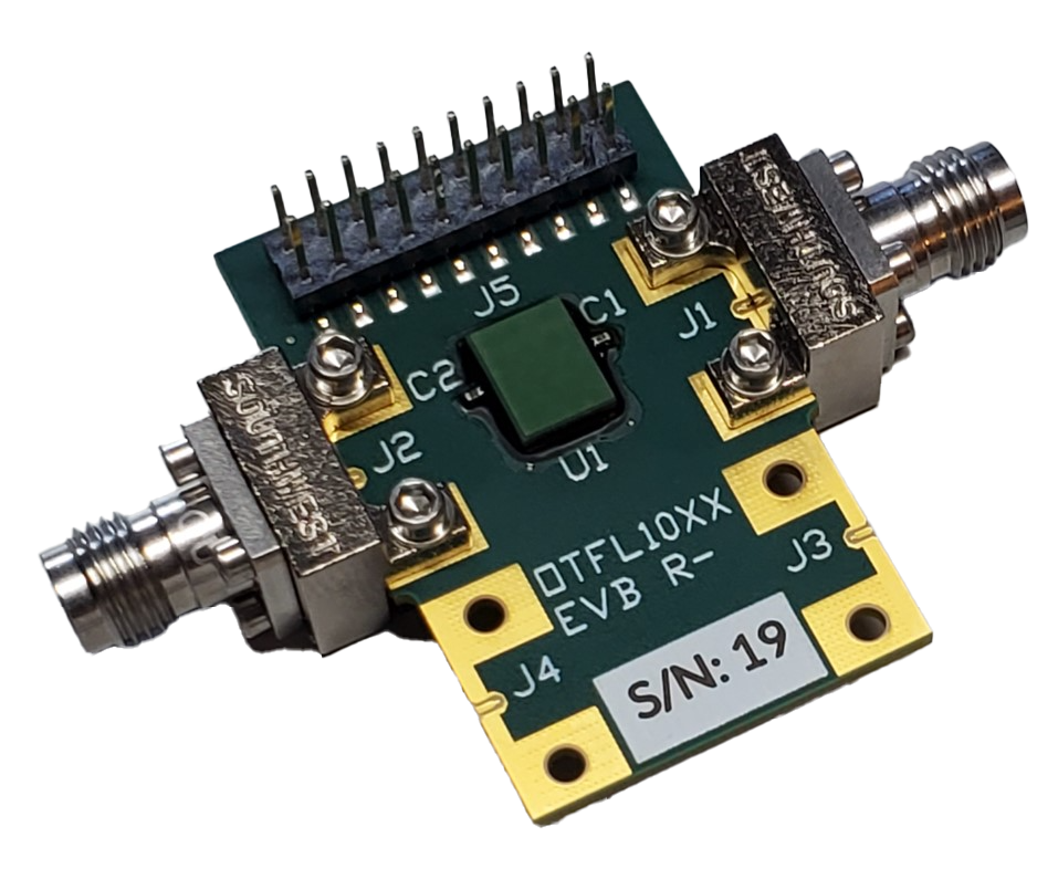
Evaluation Board
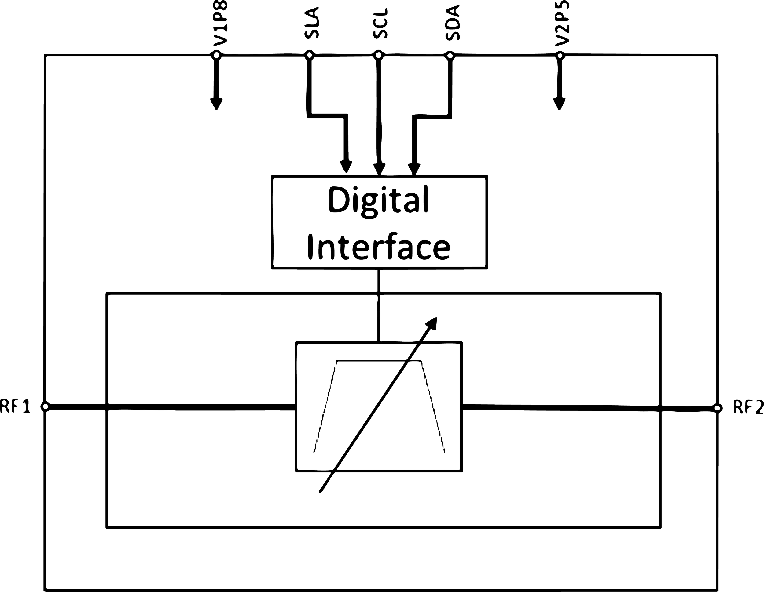
Block Diagram
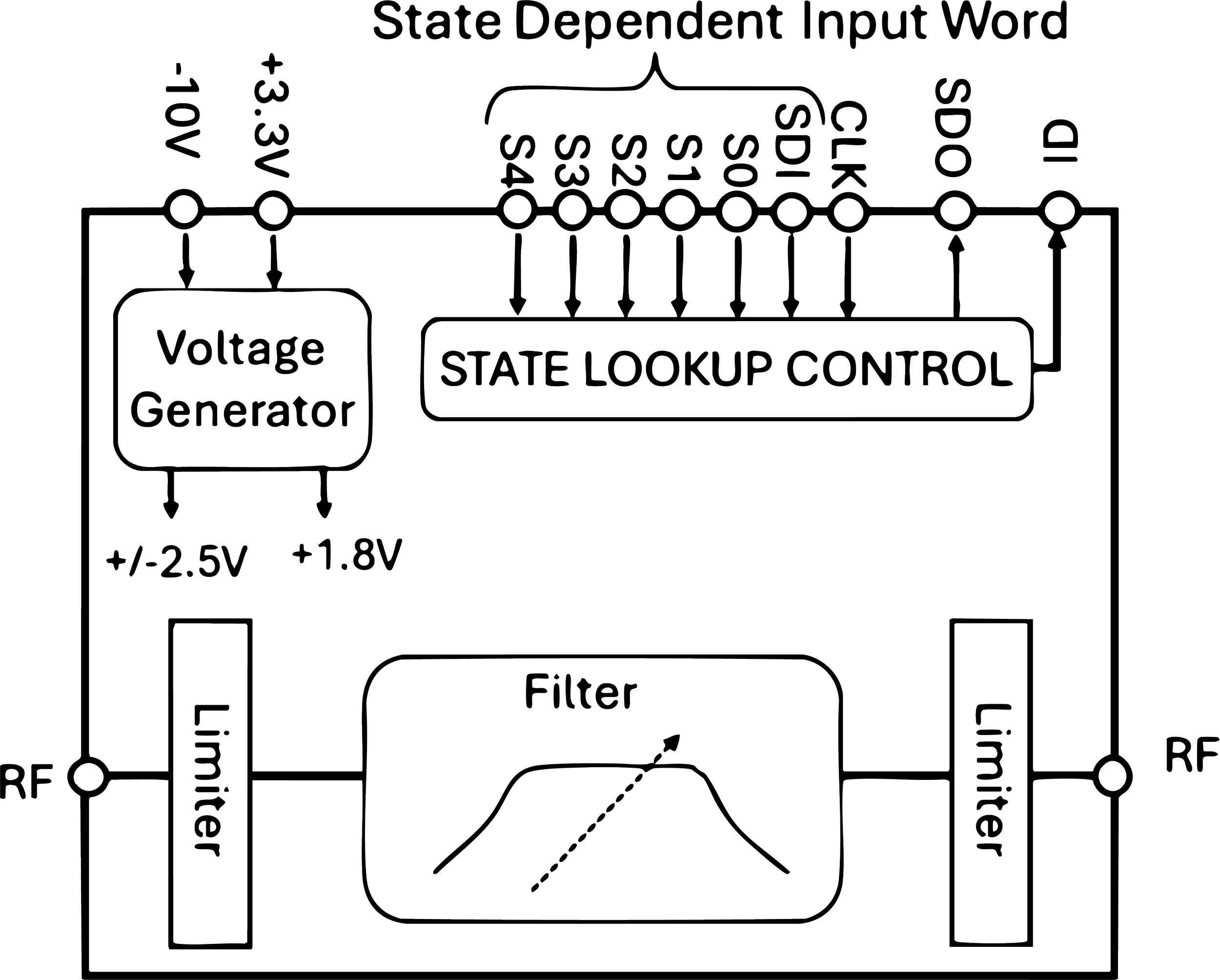
The OTFL1001 is a digitally tunable bandpass filter with 7% fractional bandwidth operating from 8 GHz to 11.5 GHz. There is also a control for shifting rejection from the above band to below band or vice-versa.
This device delivers a bandpass response over multiple selectable center frequencies for RF systems while providing 10x or more PCB area reduction in comparison to a switched filter bank or cavity tuned filter solution. These application areas include but are not limited to radio, communication, military radar, and instrumentation.
Features
Digitally Tunable Bandpass Filter from 8GHz to 11.5 GHz
256 Discrete Frequency Settings for fine resolution
Integrated Limiter for High Power Protection
Ultra Linear Design: 39 dBm IIP3
Digital Control Interface with 31 Presets
Fast Switching with Sub-200 ns Settling Time
Daisy-Chaining for Multi-Filter Systems
Compact Die Size (2.875 mm x 4.0mm)
OTFL101 2.5-7.5 GHz Tunable Filter

Evaluation Board
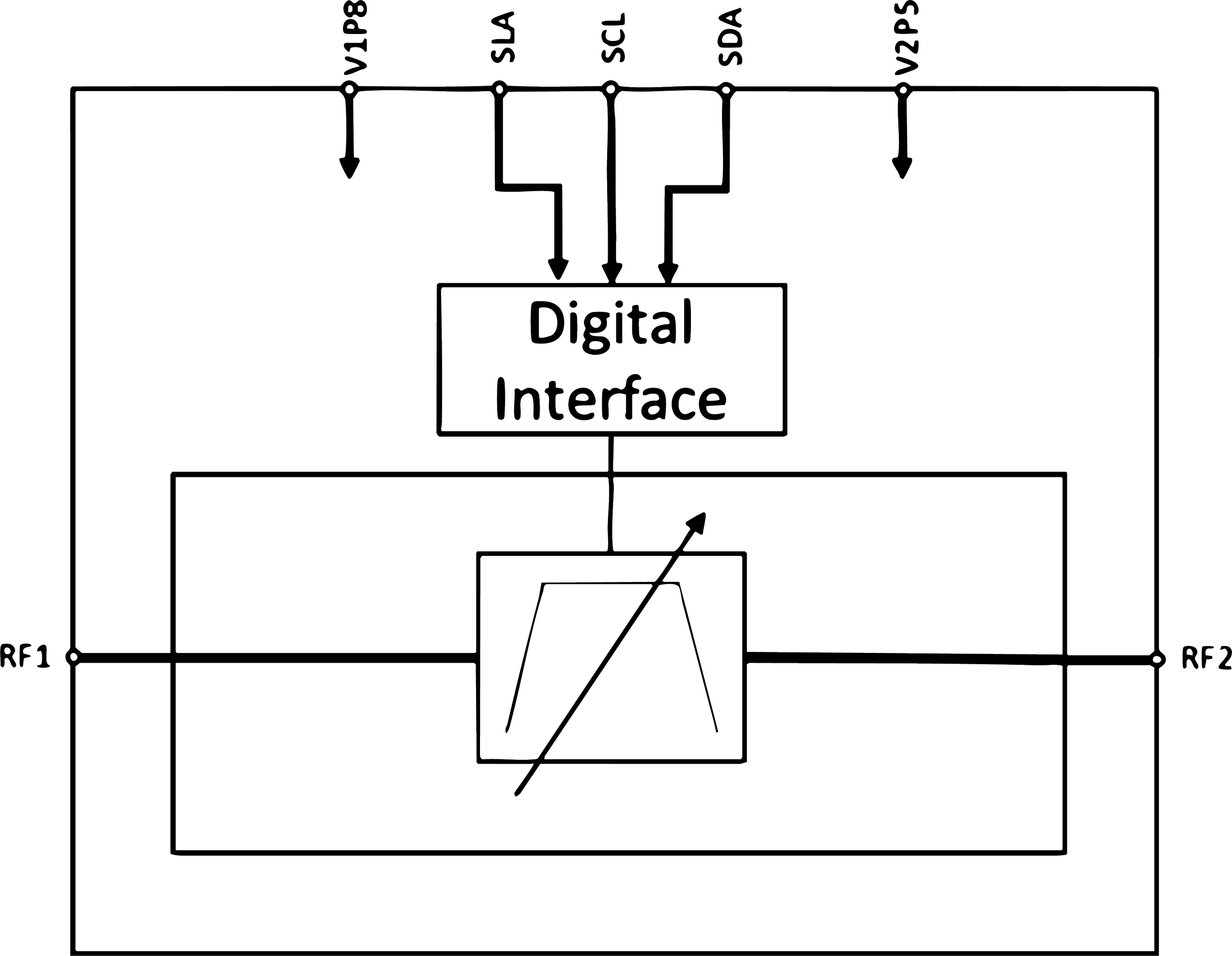
Block Diagram
The OTFL101 is a digitally tunable bandpass filter. The wide range of control with many different combinations provides flexibility of passband tuning from 2.5 GHz to 7.5 GHz. The typical insertion loss id TBD. The device delivers spur/interface removal techniques over multiple center frequencies to Rf systems while providing 10x PCB area reduction in comparison to a switched filter bank or a cavity tuned filter solution. These application areas include but are not limited to radio, communication, military radar, and instrumentation
MatLab Explorer App was developed to assist customers to use in system chain analysis and optimization. These data driven models predict amplitude and phase very accurately in response to the user defined input controls. This advanced capability enables intimate exploration of the device’s degrees of freedom.
Features
2.5 GHz to 7.5 GHz Frequency Range
Digitally Tunable
Up to 1.5 GHz of Instantaneous Bandwidth (IBW)
In Band IIP3: 47 dBm
Power Supplies: +1.8 V, +2.5 V
Single Chip Replacement for Discrete Filter Banks
Flip Chip C4 Bump
Die Dimension: 2.34 mm x 1.634 mm
OTFL201 14GHz- 24GHz Tunable Filter
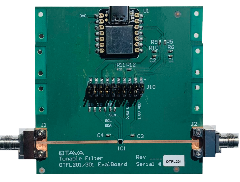
Evaluation Board
Block Diagram
The OTFL201 is a digitally tunable bandpass filter. The wide range of control (many different combinations) provides flexibility of passband tuning from 14 GHz to 24 GHz. The typical insertion loss is 5-8 dB.
This device delivers spur/interference removal techniques over multiple center frequencies to RF systems while providing 10x PCB area reduction in comparison to a switched filter bank or cavity tuned filter solution. These application areas include but not limited, radio, communication, military radar, and instrumentation.
MatLab Explorer App was developed to assist customers to use in system chain analysis and optimization. These data driven models predict amplitude and phase very accurately in response to the user defined input controls. This advanced capability enables intimate exploration of the device’s degrees of freedom.
Features
24 GHz to 40 GHz Frequency Range
Digitally Tunable
In Band IIP3: 42 dBm
Power Supplies: +1.8 V, +2.5 V
Single Chip Replacement for Discrete Filter Banks
Flip Chip C4 Bump
Die Dimension: 1.634 mm x 1.637 mm
OTFL301 24 GHz - 40 GHz Tunable Filter

Evaluation Board
Block Diagram

The OTFL301 is a digitally tunable bandpass filter. The wide range of control (many different combinations) provides flexibility of frequency tuning from 24 GHz to 40GHz. The typical insertion loss is 7 dB.
This device delivers spur/interference removal techniques over multiple center frequencies to RF systems while providing 10x PCB area reduction in comparison to a switched filter bank or cavity tuned filter solution. These application areas include but not limited, radio, communication, military radar, and instrumentation.
MatLab Explorer App was developed to assist customers to use in system chain analysis and optimization. These data driven models predict amplitude and phase very accurately in response to the user defined input controls. This advanced capability enables intimate exploration of the device’s degrees of freedom.
Features
24 GHz to 40 GHz Frequency Range
Digitally Tunable
In Band IIP3: 42 dBm
Power Supplies: +1.8 V, +2.5 V
Single Chip Replacement for Discrete Filter Banks
Flip Chip C4 Bump
Die Dimension: 1.634 mm x 1.637 mm